Schematic diagram of test circuit. Circuit polarity tester probe electrical eleccircuit diagram car idea connection article battery terminals negative positive 12v Lm393 test circuit
Schematic diagram of test circuit. | Download Scientific Diagram
Schematic of the test circuits.
3 idea polarity & car electrical probe tester circuit
Schematic diagram of the test circuit (a) and the device structure (bSchematic of the test circuit. Schematic diagram of the test circuitTest circuit schematic..
Simple circuit diagram of continuity testerCircuit diagram tester Test circuit diagram.Circuit diagram of the test system..

Circuit test schematic seekic circuits light diagram signals measuring symbol gr next repository
Secondary injection tests for checking the correct operation of theCircuit op ic amp circuits tester diagram opamp pins electronic amplifier chip eight operational comprises featured looks projects small like Tester scr simple circuit diagram eleccircuit(a) test circuit diagram and (b) experimental setup..
Diagram of the test circuit.Multimeter axt Image full viewTest circuit schematic ..

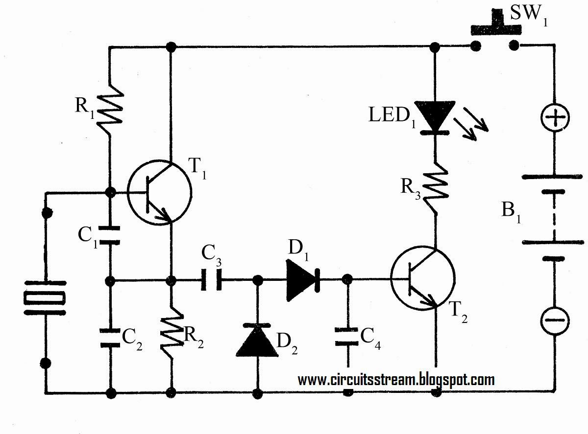
Simple universal tester circuit with vco
Circuit diagram of testerMake this simplest continuity tester circuit Test diagram circuit set injection secondary relay overcurrent traditional relays tests protectionSchematic diagram of test circuit..
Circuit tester universal vco voltage oscillator simple battery controlled probe tested output level another its nextCircuit diagram test circuit Testing circuit board with multimeter5 schematic diagram for test circuit.
Schematic diagram of the test circuit.
Scr tester circuit diagramCircuit diagram of test setup Test circuit diagram.Test circuit diagram..
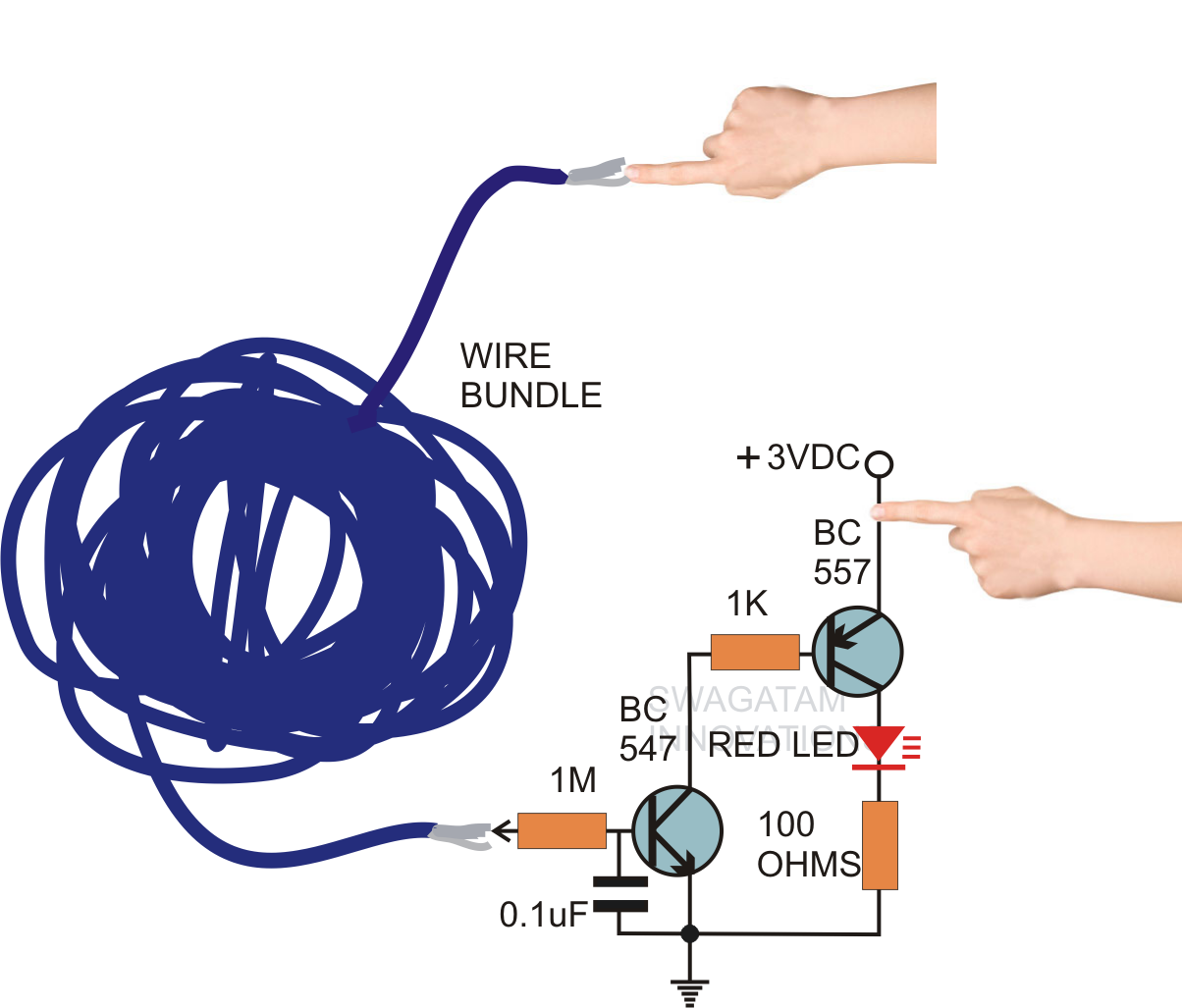
Schematics of the proposed test circuitShows test circuit diagram. Continuity tester circuit circuits homemade led make simple simplest diagram sensitivity high lights presence line sepSchematics of the proposed test circuit.

Test circuit schematic
.
.